
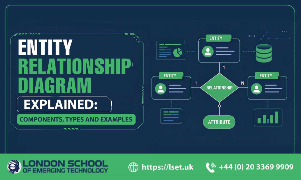
Designing a database requires more than creating tables and adding columns. Before implementing a database, developers and database professionals need to understand what information the system will store and how different pieces of data connect. An Entity Relationship Diagram provides a visual way to represent this structure.
An Entity Relationship Diagram, commonly called an ER diagram or ERD, shows entities, their attributes and the relationships between them. It can be used during database planning to provide a clear representation of how information is organised within a system.
For students, developers and professionals learning database design, understanding ER diagrams provides a useful foundation for working with relational databases and SQL.
What Is an Entity Relationship Diagram?
An Entity Relationship Diagram is a visual representation of entities and the relationships between them within a database system.
An entity represents something about which information is stored. Depending on the application, an entity could be a customer, student, product, employee or order.
For example, an online shopping system might contain entities such as Customer, Product and Order. Each entity can have attributes that describe it, while relationships explain how the entities are connected.
An ERD can therefore provide a conceptual view of database structure before the design is translated into database tables.
Key Components of an ER Diagram
Understanding the main ER diagram components makes it easier to read and create database models.
Entities
An entity represents an object or concept about which data needs to be stored. In a relational database, entities are commonly represented as tables when the design is implemented.
For an education management system, possible entities could include Student, Course, Instructor and Enrolment.
Attributes
Attributes describe the characteristics of an entity. For a Student entity, attributes could include Student ID, Name, Email and Date of Birth.
When an ERD is converted into a relational database, these attributes can become columns within the corresponding table.
Relationships
Relationships describe how entities are associated with one another. For example, a Customer places an Order, while a Student enrols in a Course.
Relationships help developers understand how records in different tables should connect.
Primary Keys
A primary key identifies a record uniquely within a table. For example, Student ID could uniquely identify each student.
Primary keys are an important part of database design because they distinguish individual records.
Foreign Keys
A foreign key creates a connection between related tables by referring to a key in another table.
For example, an Order table might include Customer ID as a foreign key that references the Customer table. This establishes a connection between orders and their customers.
Types of Relationships in an ER Diagram
Relationships describe how many records in one entity can be associated with records in another entity. Common relationship types include one-to-one, one-to-many, and many-to-many.
One to One Relationship
A one-to-one relationship means that one record in one entity is associated with one record in another entity.
For example, a system might have a Person entity and a Passport entity where each person is associated with one passport record.
One-to-Many Relationship
A one-to-many relationship occurs when one record can be associated with multiple records in another entity.
For example, one customer can place multiple orders, while each order can belong to one customer. This creates a one-to-many relationship between Customer and Order.
Many-to-Many Relationship
A many-to-many relationship occurs when multiple records on one side can be associated with multiple records on the other side.
For example, a student can enrol in several courses, while each course can have several students.
In a relational database, many-to-many relationships are commonly represented through an additional linking entity or table. This table contains foreign keys that reference the related entities.
Entity Relationship Diagram Example
Consider a simple online learning platform.
The database could contain the following entities:
Student
Student ID
Name
Email
Course
Course ID
Course Name
Level
Enrolment
Enrolment ID
Student ID
Course ID
Enrolment Date
The Student and Course entities have a many-to-many relationship because one student can enrol in multiple courses and one course can have multiple students.
The Enrolment entity can represent this connection. Student ID can reference the Student entity, while Course ID can reference the Course entity.
This approach provides a structured way to represent the relationship and can then be translated into relational database tables.
What Is Cardinality in an ER Diagram?
Cardinality describes the number of instances that can participate in a relationship. Common examples include one-to-one, one-to-many, and many-to-many relationships.
Cardinality is important because it communicates how entities should be connected. For example, identifying a relationship as one-to-many tells the database designer that one record on one side can be associated with multiple records on the other side.
Different ERD notations represent cardinality in different ways. Crow’s foot notation is one commonly used approach for displaying these relationships.
How to Create an Entity Relationship Diagram
You can create an ERD through a series of practical steps.
1. Identify the Entities
Start by identifying the main objects or concepts within the system.
2. List the Attributes
Determine which information needs to be stored for each entity.
3. Identify Primary Keys
Choose an attribute or set of attributes that can uniquely identify records.
4. Define Relationships
Determine how the entities interact with one another.
5. Establish Cardinality
Decide whether each relationship is one to one, one to many or many to many.
6. Review the Database Model
Check the diagram for missing relationships, unnecessary duplication and unclear connections before implementing the database.
Why ER Diagrams Matter in Database Design
An ERD provides a visual model that helps developers, database designers, and other project stakeholders understand database requirements before implementation.
It can also make discussions about tables, relationships and data structures easier because the proposed design can be reviewed visually.
For learners developing full stack development skills, database modelling is particularly relevant because applications often depend on well-structured data. LSET’s Full Stack Java course includes database-related learning areas such as ERD creation, database tables and normalisation.
Final Thoughts
An Entity Relationship Diagram provides a structured way to visualise database entities, attributes and relationships before a database is implemented. Understanding entities, primary keys, foreign keys, relationships and cardinality can help learners develop a stronger foundation in database design.
Whether you are learning SQL, developing a web application or studying full stack development, practising ERD creation can help you understand how different parts of a database connect.
Starting with simple examples such as students and courses, customers and orders or products and categories can provide a practical way to learn database modelling before progressing towards more complex systems.